State space visualization examples
(This page is under construction)
Alternating Bit Protocol
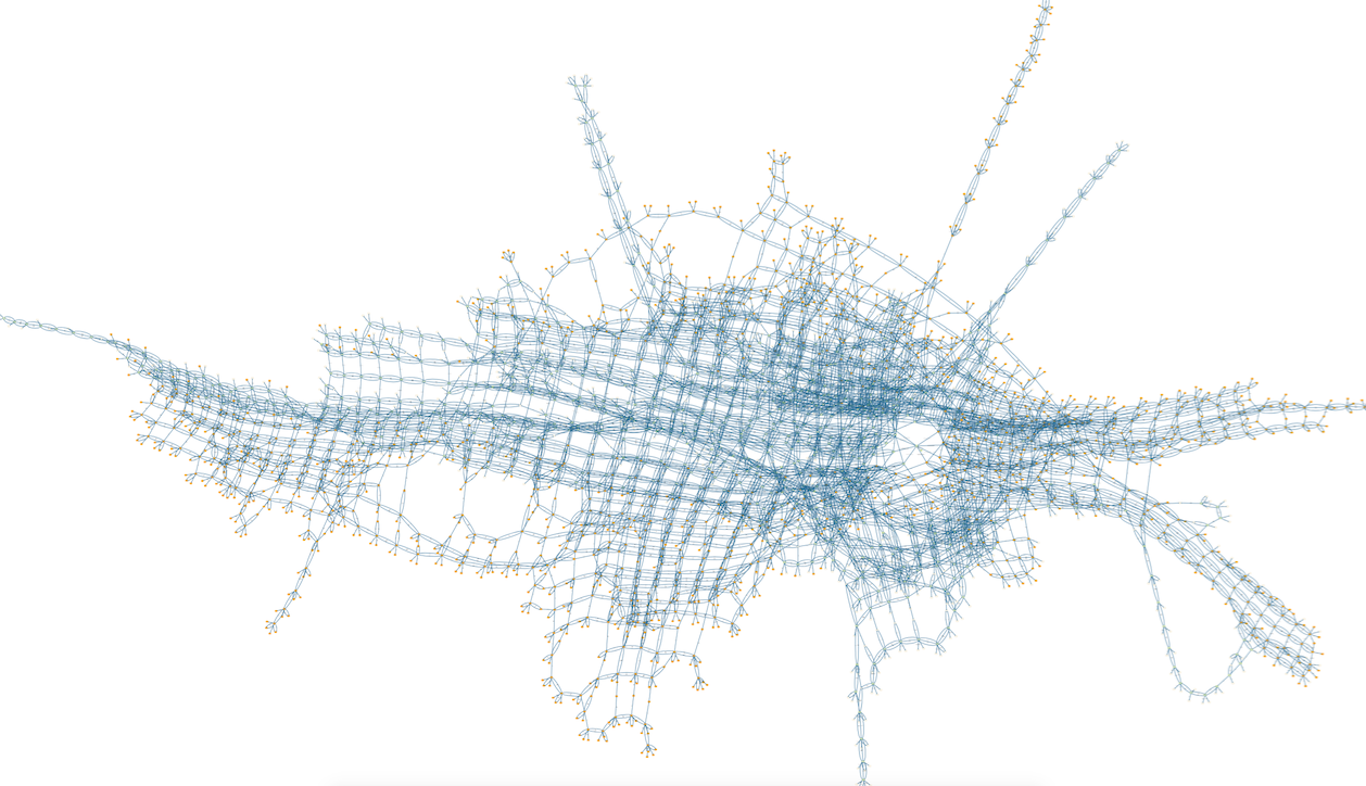
This is a visualisation of 3643 states and 11115 transitions of a TLA+ model of the alternating bit protocol, as distributed with the TLA+ tools. This model (MCAlternatingBit.tla) was loaded with ProB for TLA+, the model checker run for a few seconds and then the command "State Space Fast Rendering" with options (scale,fast) was used.
The goal predicate rBit=1 was used; those states satisfying this predicate are shown in orange.
Below is a projection of this state space onto the expression (rBit,sBit), using the "Custom Transition Diagram" feature of ProB:
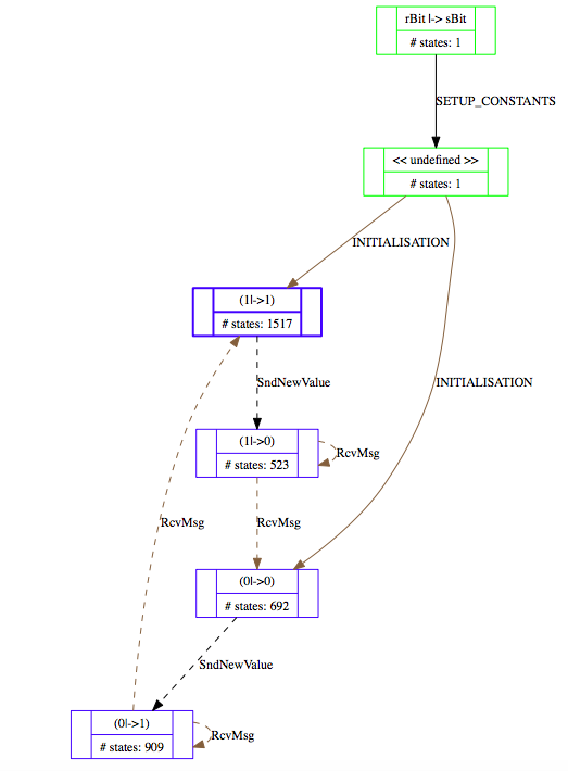
More details about this statespace projection feature can be found in our ICFEM'15 article.
The main file of the model is:
--------------------------- MODULE MCAlternatingBit -------------------------
EXTENDS AlternatingBit, TLC

INSTANCE ABCorrectness

CONSTANTS msgQLen, ackQLen

SeqConstraint == /\ Len(msgQ) \leq msgQLen
                 /\ Len(ackQ) \leq ackQLen

SentLeadsToRcvd == \A d \in Data : (sent = d) /\ (sBit # sAck) ~> (rcvd = d)
=============================================================================

ImpliedAction == [ABCNext]_cvars

TNext == WF_msgQ(~ABTypeInv')
TProp == \A d \in Data : (sent = d) => [](sent = d)

CSpec == ABSpec /\ TNext

DataPerm == Permutations(Data)
==============================================================
MCInnerFIFO
This is a visualisation of 3866 states and 9661 transitions of a TLA+ model of a FIFO, as distributed with the TLA+ tools. This model (MCInnerFIFO) was loaded with ProB for TLA+ and the model checker run so that all states with queue size greater than qLen (3) were ignored, i.e., no successor states were computed (this can be set by defining SCOPE==card(q)<=qLen). The colour indicates the length of the queue variable q of the model (gray=0,blue=1,red=2, green=3, lightgray=4) .
Below is a projection of this state space onto the expression card(q), using the "Custom Transition Diagram" feature of ProB:

RushHour
This is a visualisation of the Rush_Hour_Puzzle Rush Hour puzzle B model, at the moment that ProB has found a solution to the goal predicate (red car moved out of the grid). The solution node(s) are marked in orange and the prism option was used.
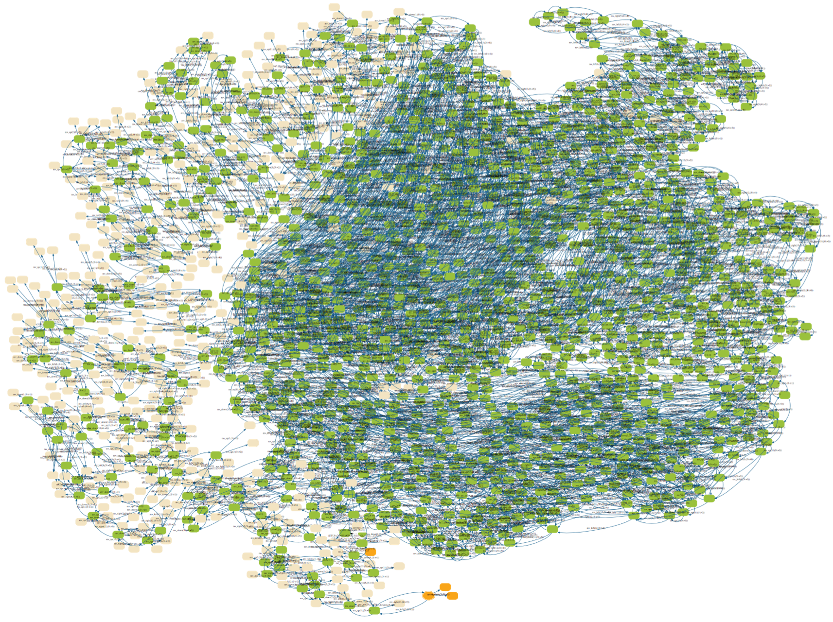
Here is a visualisation of the full state space of 4782 nodes and 29890 transitions, using the scale option this time:
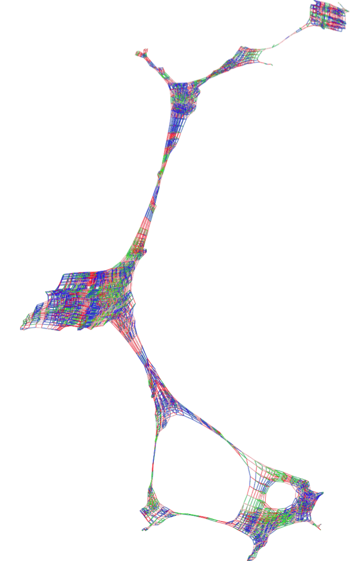
CAN Bus
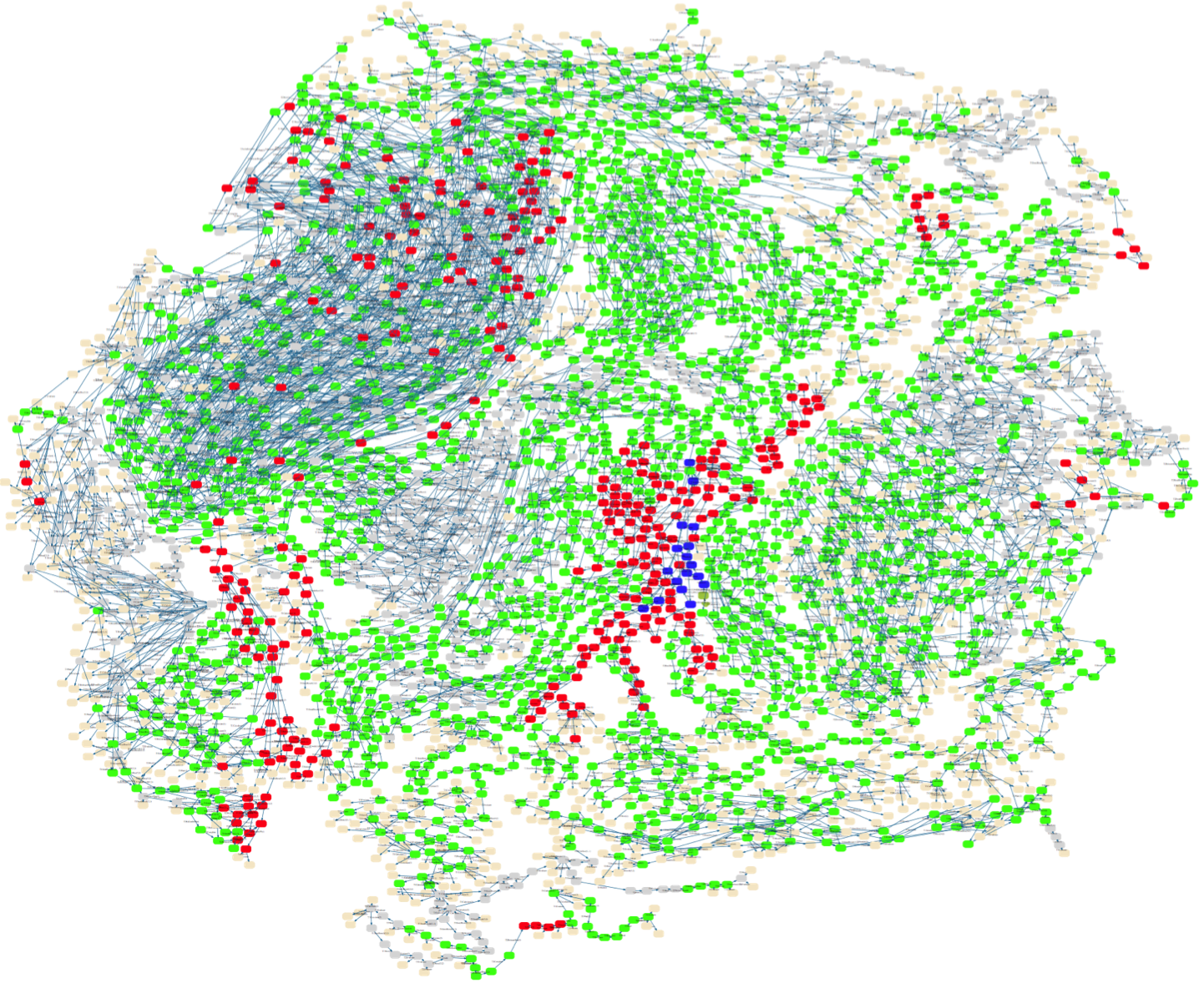
This is a visualisation of the statespace of an Event-B model of a CAN Bus. The colours indicate the size of the BUSwrite variable (gray=0,blue=1,red=2, green=3, lightgray=4).
Hanoi (6 Discs)
This is a visualisation of the statespace of a B model of the towers of Hanoi for 6 discs. The state space contains 731 nodes and 2186 nodes.
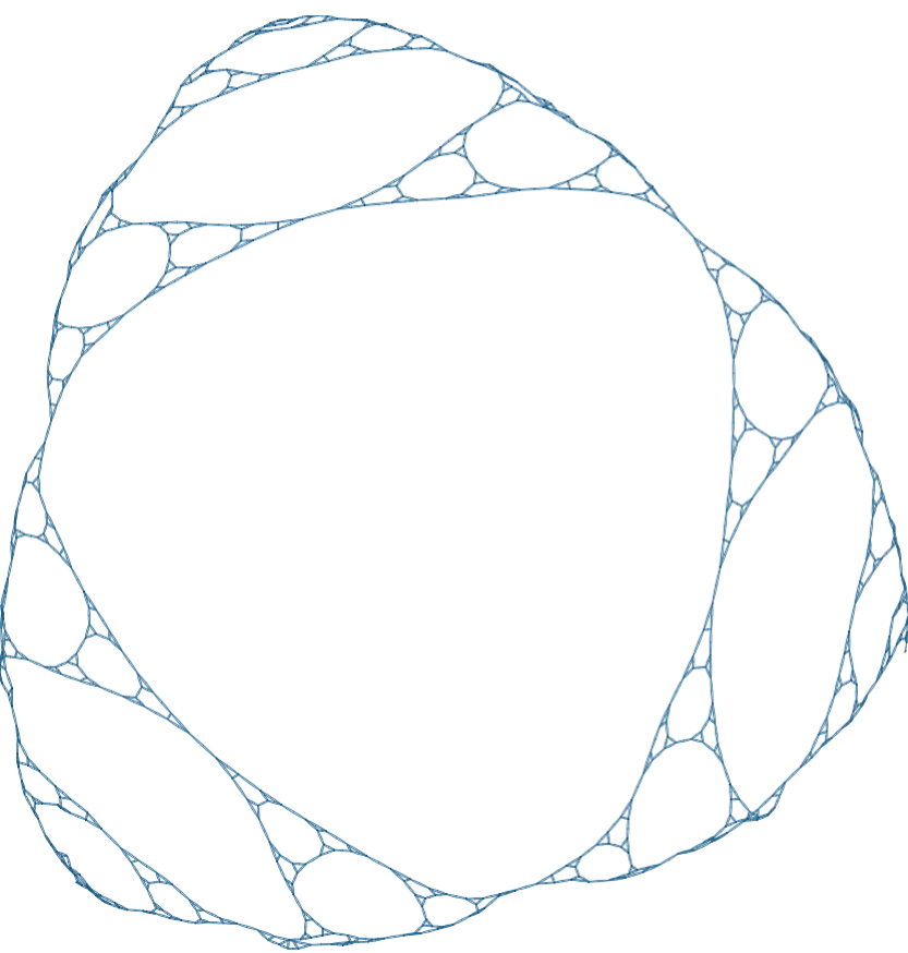
One can observe that this figure resembles a Sierpinski triangle. This is no coincidence, the state space of Hanoi is one.
Below is a projection of this state space onto the expression card(on(dest))), using the "Custom Transition Diagram" feature of ProB:

Threads - Partial Order Reduction
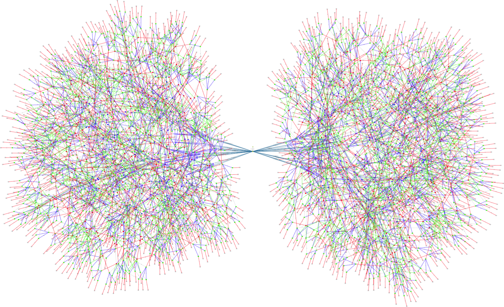
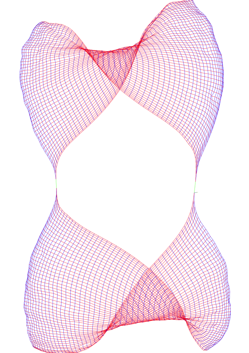
This is the visualisation of a simple threads model, of two threads with n=51 steps before a synchronisation occurs and threads start again. The state space contains 5410 nodes. One can clearly see two synchronisation points on the left-hand side and right-hand side, and that in between synchronisation the processes simply interleave.
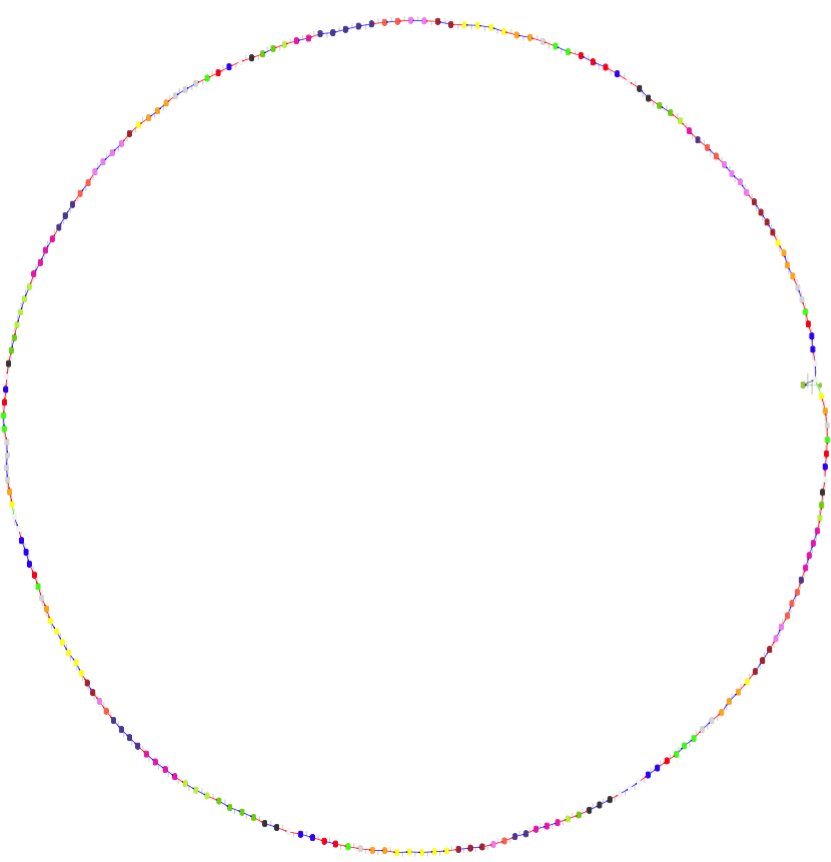
With partial order reduction, the state space is reduced to 208 states:
Here is the B source code of the model:
MACHINE Threads51
/* Two simple threads communicating from time to time
This kind of situation should happen quite often in controller systems
A partial-order reduction can hopefully reduce the interleavings
*/
DEFINITIONS
 ASSERT_LTL1 == "F deadlock(Step1_p1,Step1_p2)";
 HEURISTIC_FUNCTION == pc1 // for sfdp colouring
CONSTANTS n
PROPERTIES n = 51 /* n=51: 208 states with POR (deadlock checking), 5410 without */
VARIABLES pc1,pc2, v1,v2
INVARIANT
pc1 : NATURAL & pc2:NATURAL &
v1 :  INTEGER & v2:INTEGER
INITIALISATION pc1,pc2,v1,v2 := 0,0,0,0
OPERATIONS
 Step1_p1 = PRE pc1<n THEN /* maybe the fact that we have a decreasing variant has an influence on POR ? In Event-B this event would be convergent */
     pc1 := pc1+1|| v1 := v1+1
 END;
 Step1_p2 = PRE pc2<n /* & pc1=n manual POR */
             THEN /* also a convergent event (variant n-pc2) */
     pc2 := pc2+1 || v2 := v2+1
 END;
 Sync = PRE pc1=n & pc2=n THEN
    pc1, pc2 := 0,0 ||
    v1,v2 := v1 mod 2, v2 mod 2
 END
END
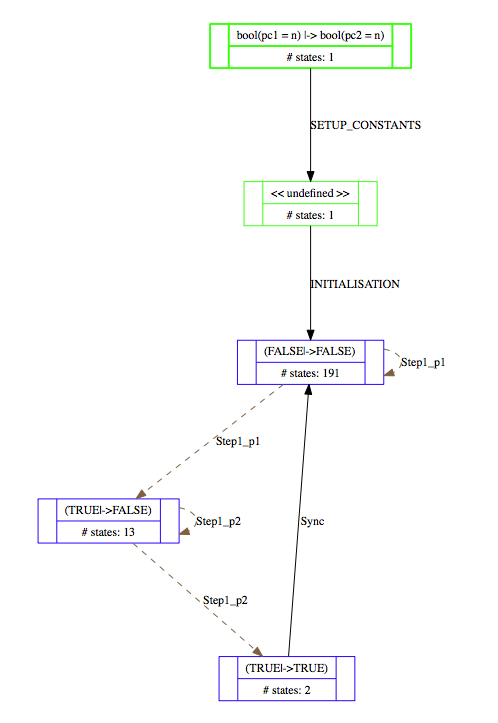
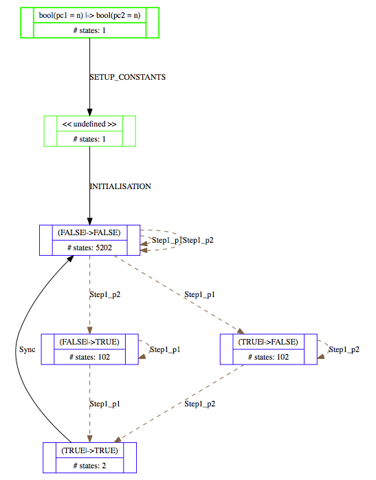
Below are projections of the above state spaces onto the expression (bool(pc1=n),bool(pc2=n)), using the "Custom Transition Diagram" feature of ProB.
The first shows the projection without partial order reduction:
With partial order reduction, one can see that the Step1_p1 events now all occur before the Step1_p2 events:
