Generating UML Sequence Charts: Difference between revisions
Created page with "= UML Sequence Charts for Traces ProB has a new experimental feature to generate a UML sequence chart from the current animation trace. It currently only works for classical..." |
|||
| (25 intermediate revisions by 2 users not shown) | |||
| Line 1: | Line 1: | ||
= | === Installation and Using === | ||
ProB has a new experimental feature to generate a UML sequence chart from the current animation trace. | ProB has a new experimental feature to generate a UML sequence chart from the current animation trace using [https://plantuml.com PlantUML]. | ||
It currently | The feature is available in ProB CLI, ProB Tcl/Tk and ProB2-UI. | ||
It currently works for classical B and TLA+ models and you need to copy the [https://plantuml.com/download plantuml.jar] file to ProB's lib folder. The file should be named plantuml.jar (without any version numbers). | |||
You can also use the command-line version of ProB to install it | |||
<pre> | |||
probcli --install plantuml | |||
</pre> | |||
This should generate output similar to this: | |||
<pre> | |||
Installing component plantuml from https://github.com/plantuml/plantuml/releases/download/v1.2024.7/ | |||
--> curl -L https://github.com/plantuml/plantuml/releases/download/v1.2024.7/plantuml-epl-1.2024.7.jar -o .../lib/plantuml.jar | |||
Installation complete | |||
</pre> | |||
=== Specifying the Actors | For ProB2-UI a dialog will pop-up when trying to use the feature giving you instructions on where to put the plantuml.jar file. | ||
=== Using the Command === | |||
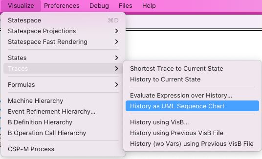
It is available in the Visualize menu of Tcl/Tk: | |||
[[file:ProBUMLSeqChartCmd.png|center||300px]] | |||
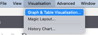
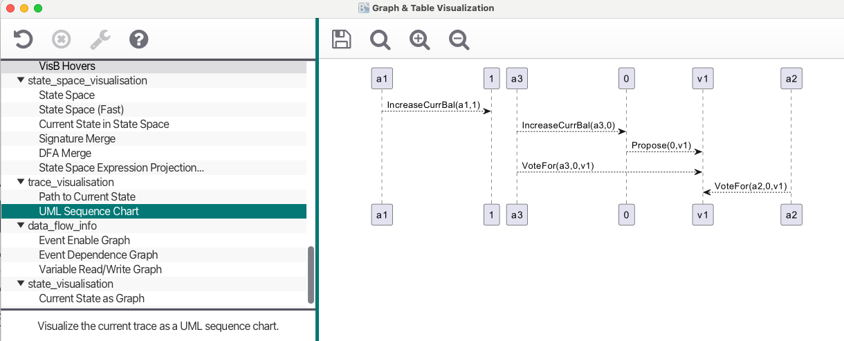
The UML sequence chart is also available in ProB2-UI in the Graph & Table Visualisation View accessible in the Visualisation menu. | |||
[[file:ProBUMLSeqChartProB2UICmd.png|center||300px]] | |||
[[file:ProBUMLSeqChartProB2UIDialog.png|center||500px]] | |||
=== Specifying the Actors === | |||
For every B Operation Op that you want to visualise you need to add a definition | For every B Operation Op that you want to visualise you need to add a definition | ||
| Line 13: | Line 39: | ||
The definition should either return | The definition should either return | ||
* a couple (ActorFrom,ActorTo) specifying the name of the actor sending the message (ActorFrom) and the one receiving the message (ActorTo). You can use strings or other values (which will be converted to strings). | * the empty string, meaning this operation should be ignored | ||
* a triple (ActorFrom,ArrowStyle,ActorTo), where the actors are like above and ArrowStyle is a string representing a valid plantUML arrow. | * a couple <tt>(ActorFrom,ActorTo)</tt> specifying the name of the actor sending the message (ActorFrom) and the one receiving the message (ActorTo). You can use strings or other values (which will be converted to strings). | ||
* a triple <tt>(ActorFrom,ArrowStyle,ActorTo)</tt>, where the actors are like above and ArrowStyle is a string representing a valid plantUML arrow. | |||
* a triple <tt>(ActorFrom,ArrowStyle,ArrowSuffix,ActorTo)</tt>, where the actors and arrow style are like above and ArrowSuffix is a string representing a valid plantUML arrow suffix. | |||
* a record <tt>rec(from:ActorFrom,to:ActorTo,arrow:ArrowStyle,suffix:ArrowSuffix)</tt>. Note that the arrow fields are optional. | |||
Currently these arrow styles are supported: | Currently these arrow styles are supported: | ||
* | * '''-->''' | ||
* < | * '''->''' | ||
* | * '''->x''' | ||
* | * '''->>''' | ||
* '''-\\''' | |||
* '''\\\\-''' | |||
* '''//--''' | |||
* '''->o''' | |||
* '''o\\\\--''' | |||
* '''<->''' | |||
* '''<->o''' | |||
* '''-[#green]>''' | |||
* '''-[#green]->''' | |||
* '''-[#blue]->''' | |||
* '''-[#red]->''' | |||
* '''-[#red]>''' | |||
* '''-[#0000FF]->''' | |||
* '''<-''' | |||
* '''<--''' | |||
Optionally you can add these suffixes: | Optionally you can add these suffixes: | ||
* | * '''++''' (activate the target) | ||
* | * '''--''' (deactivate source) | ||
* | * '''**''' (create an instance of target) | ||
* <pre>!!</ | * '''!!''' (destroy an instance of target) | ||
== Example == | |||
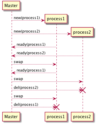
The following diagram can be created using the model below after animating and then using the command above. | |||
[[file:ProBUMLSeqCharScheduler.png|center||300px]] | |||
And here is the well-known scheduler example with example SEQUENCE_CHART definitions: | |||
<pre> | |||
MACHINE scheduler_UML | |||
SETS | |||
PID = {process1,process2,process3} | |||
VARIABLES active, ready, waiting | |||
DEFINITIONS | |||
"CHOOSE.def"; | |||
SEQUENCE_CHART_INITIALISATION == ""; // ignore | |||
SEQUENCE_CHART_new(pp) == ("Master", "-->","**",pp); | |||
SEQUENCE_CHART_del(pp) == ("Master", "-->","!!",pp); | |||
SEQUENCE_CHART_ready(pp) == (pp, "-->","Master"); | |||
SEQUENCE_CHART_swap == ("Master", "-->","--",CHOOSE(active)) | |||
INVARIANT | |||
active <: PID & | |||
ready <: PID & | |||
waiting <: PID & | |||
(ready /\ waiting) = {} & | |||
active /\ (ready \/ waiting) = {} & | |||
/*@label "SAF" */ card(active) <= 1 & | |||
((active = {}) => (ready = {})) | |||
INITIALISATION | |||
active := {} || ready := {} || waiting := {} | |||
OPERATIONS | |||
new(pp) = | |||
SELECT | |||
pp : PID & | |||
pp /: active & | |||
pp /: (ready \/ waiting) | |||
THEN | |||
waiting := (waiting \/ { pp }) | |||
END; | |||
del(pp) = | |||
SELECT | |||
pp : waiting | |||
THEN | |||
waiting := waiting - {pp} | |||
END; | |||
ready(rr) = | |||
SELECT | |||
rr : waiting | |||
THEN | |||
waiting := (waiting - {rr}) || | |||
IF (active = {}) THEN | |||
active := {rr} | |||
ELSE | |||
ready := ready \/ {rr} | |||
END | |||
END; | |||
swap = | |||
SELECT | |||
active /= {} | |||
THEN | |||
waiting := (waiting \/ active) || | |||
IF (ready = {}) THEN | |||
active := {} | |||
ELSE | |||
ANY pp WHERE pp : ready | |||
THEN | |||
active := {pp} || | |||
ready := ready - {pp} | |||
END | |||
END | |||
END | |||
END | |||
</pre> | |||
Revision as of 09:18, 18 September 2024
Installation and Using
ProB has a new experimental feature to generate a UML sequence chart from the current animation trace using PlantUML. The feature is available in ProB CLI, ProB Tcl/Tk and ProB2-UI. It currently works for classical B and TLA+ models and you need to copy the plantuml.jar file to ProB's lib folder. The file should be named plantuml.jar (without any version numbers).
You can also use the command-line version of ProB to install it
probcli --install plantuml
This should generate output similar to this:
Installing component plantuml from https://github.com/plantuml/plantuml/releases/download/v1.2024.7/
 --> curl -L https://github.com/plantuml/plantuml/releases/download/v1.2024.7/plantuml-epl-1.2024.7.jar -o .../lib/plantuml.jar
Installation complete
For ProB2-UI a dialog will pop-up when trying to use the feature giving you instructions on where to put the plantuml.jar file.
Using the Command
It is available in the Visualize menu of Tcl/Tk:

The UML sequence chart is also available in ProB2-UI in the Graph & Table Visualisation View accessible in the Visualisation menu.


Specifying the Actors
For every B Operation Op that you want to visualise you need to add a definition
SEQUENCE_CHART_Op
in your DEFINITIONS. The definition can take arguments, in which case the actual arguments in the trace are passed to the definition. The definition can take fewer arguments (but not more) than the B operation.
The definition should either return
- the empty string, meaning this operation should be ignored
- a couple (ActorFrom,ActorTo) specifying the name of the actor sending the message (ActorFrom) and the one receiving the message (ActorTo). You can use strings or other values (which will be converted to strings).
- a triple (ActorFrom,ArrowStyle,ActorTo), where the actors are like above and ArrowStyle is a string representing a valid plantUML arrow.
- a triple (ActorFrom,ArrowStyle,ArrowSuffix,ActorTo), where the actors and arrow style are like above and ArrowSuffix is a string representing a valid plantUML arrow suffix.
- a record rec(from:ActorFrom,to:ActorTo,arrow:ArrowStyle,suffix:ArrowSuffix). Note that the arrow fields are optional.
Currently these arrow styles are supported:
- -->
- ->
- ->x
- ->>
- -\\
- \\\\-
- //--
- ->o
- o\\\\--
- <->
- <->o
- -[#green]>
- -[#green]->
- -[#blue]->
- -[#red]->
- -[#red]>
- -[#0000FF]->
- <-
- <--
Optionally you can add these suffixes:
- ++ (activate the target)
- -- (deactivate source)
- ** (create an instance of target)
- !! (destroy an instance of target)
Example
The following diagram can be created using the model below after animating and then using the command above.

And here is the well-known scheduler example with example SEQUENCE_CHART definitions:
MACHINE scheduler_UML
SETS
	PID  = {process1,process2,process3}
VARIABLES active, ready, waiting
DEFINITIONS
      "CHOOSE.def";
      SEQUENCE_CHART_INITIALISATION == ""; // ignore
      SEQUENCE_CHART_new(pp) == ("Master", "-->","**",pp);
      SEQUENCE_CHART_del(pp) == ("Master", "-->","!!",pp);
      SEQUENCE_CHART_ready(pp) == (pp, "-->","Master");
      SEQUENCE_CHART_swap == ("Master", "-->","--",CHOOSE(active))
INVARIANT
           active <: PID &
           ready <: PID   &
           waiting <: PID &
           (ready /\ waiting) = {} &
           active /\ (ready \/ waiting) = {} &
           /*@label "SAF" */ card(active) <= 1 &
           ((active = {})  => (ready = {}))
INITIALISATION
	active := {} || ready := {} || waiting := {}
OPERATIONS
new(pp) =
	SELECT
		pp : PID  &
		pp /: active &
		pp /: (ready \/ waiting)
	THEN
		waiting := (waiting \/ { pp })
	END;
del(pp) =
	SELECT
		pp : waiting
	THEN
		waiting := waiting - {pp}
	END;
ready(rr) =
        SELECT
                rr : waiting
        THEN
                waiting := (waiting - {rr}) ||
                IF (active = {}) THEN
                   active := {rr}
                ELSE
                   ready := ready \/ {rr}
                END
        END;
swap =
        SELECT
                active /= {}
        THEN
                waiting := (waiting \/ active) ||
                IF (ready = {}) THEN
                   active := {}
                ELSE
                   ANY pp WHERE pp : ready
                   THEN
                       active := {pp} ||
                       ready := ready - {pp}
                   END
                END
        END
END